LaTeX Graphics using TikZ: A Tutorial for Beginners (Part 4)—Circuit Diagrams Using Circuitikz
Part 1 | Part 2 | Part 3 | Part 4 | Part 5
Author: Josh Cassidy (August 2013)
This five-part series of articles uses a combination of video and textual descriptions to teach the basics of creating LaTeX graphics using TikZ. These tutorials were first published on the original ShareLateX blog site during August 2013; consequently, today's editor interface (Overleaf) has changed considerably due to the development of ShareLaTeX and the subsequent merger of ShareLaTeX and Overleaf. However, much of the content is still relevant and teaches you some basic LaTeX—skills and expertise that will apply across all platforms.
In this post we're going to show you how to draw simple electrical circuits in a LaTeX document.
To do this we are going to use the circuitikz package which is based on the TikZ package.
To get started we load up the circuitikz package.
\usepackage{circuitikz}
We don't need to load the TikZ package as well because it automatically gets loaded with circuitikz.
To draw a diagram we use the circuitikz environment. We then fill the environment with a single \draw command ending in a semicolon.
\begin{circuitikz} \draw
<circuitikz code>
;
\end{circuitikz}
The general format is then a pair of co-ordinates followed by a link and then the next pair of co-ordinates. You can then keep adding further links and co-ordinates like a chain.
The link could simply be a line which is achieved using two dashes, or it could be an electrical component. To add a component on a line we use the keyword to followed by square brackets containing the name of the component. For example, we'll start at (0,0) and head towards (0,4) adding a battery in. We'll then add an ammeter in on the way to (4,4) followed by a simple line to (4,0). We'll complete the circuit by adding a lamp in on the way back (0,0):
\begin{circuitikz} \draw
(0,0) to[battery] (0,4)
  to[ammeter] (4,4) -- (4,0)
  to[lamp] (0,0)
;
\end{circuitikz}
This is what the diagram looks like compiled:
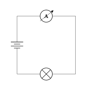
Now let's add a voltmeter in parallel to the lamp. To do this we want to branch off the bottom line part way along, then drop down, insert the meter, and then join back up with the bottom line before its end:
\begin{circuitikz} \draw
(0,0) to[battery] (0,4)
  to[ammeter] (4,4) -- (4,0)
  to[lamp] (0,0)
(0.5,0) -- (0.5,-2)
  to[voltmeter] (3.5,-2) -- (3.5,0)
;
\end{circuitikz}
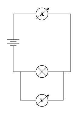
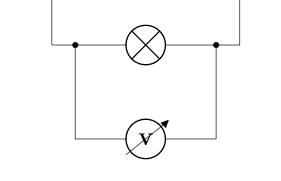
If we wanted to make the points where the lines join into proper terminals represented by circles, we could add *-* into the square brackets where we added the lamp in. This will add terminals in at the co-ordinates either side of the component. Therefore we need to shorten the lines either side of the lamp so that the terminals appear at our line joins, and then we need to fill in the gaps:
\begin{circuitikz} \draw
(0,0) to[battery] (0,4)
  to[ammeter] (4,4) -- (4,0) -- (3.5,0)
  to[lamp, *-*] (0.5,0) -- (0,0)
(0.5,0) -- (0.5,-2)
  to[voltmeter] (3.5,-2) -- (3.5,0)
;
\end{circuitikz}
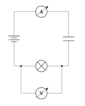
Next we'll add a capacitor in between the lamp and ammeter.
We specify a capacitor with a capital C:
\begin{circuitikz} \draw
(0,0) to[battery] (0,4)
  to[ammeter] (4,4)
  to[C] (4,0) -- (3.5,0)
  to[lamp, *-*] (0.5,0) -- (0,0)
(0.5,0) -- (0.5,-2)
  to[voltmeter] (3.5,-2) -- (3.5,0)
;
\end{circuitikz}
Often we'll want to add labels to our diagrams to give the reader more information. To be able to include electrical units in our labels we need to add the siunitx option into the \usepackage command:
\usepackage[siunitx]{circuitikz}
We could add a label to the ammeter like this:
to[ammeter, l=2<\ampere>]

The l tells LaTeX we are adding a label. Notice that we put the unit commands in pointed brackets. As we're using SI units we could add an SI prefix in. We could also move the label to below the symbol by adding underscore immediately after the l:
to[ammeter, l_=2<\milli\ampere>]

As we are displaying current we could place the label next to an arrow on the line by changing the l to an i:
to[ammeter, i_=2<\milli\ampere>]

Let's add some labels in next to the capacitor and the voltmeter. With the capacitor we can just begin the label with an equals following the capital C:
\begin{circuitikz} \draw
(0,0) to[battery] (0,4)
  to[ammeter, i_=2<\milli\ampere>] (4,4)
  to[C=3<\farad>] (4,0) -- (3.5,0)
  to[lamp, *-*] (0.5,0) -- (0,0)
(0.5,0) -- (0.5,-2)
  to[voltmeter, l=3<\kilo\volt>] (3.5,-2) -- (3.5,0)
;
\end{circuitikz}
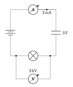
We could also change the colour of a component like this:
to[voltmeter, l=3<\kilo\volt>, color=red]

We can change the size of the diagram by adding a scaling factor in as an option at the end of the \begin command:
\begin{circuitikz}[scale=2] \draw
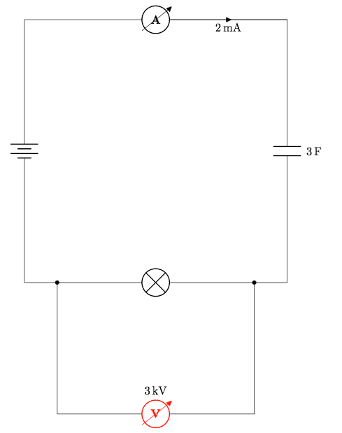
Notice that the components stay the same size but the spacing between everything changes.
Let's finish this post by looking at a selection of other components we could use:
\begin{circuitikz}
\draw
(0,0) to[R, o-o] (2,0)
(4,0) to[vR, o-o] (6,0)
(0,2) to[transmission line, o-o] (2,2)
(4,2) to[closing switch, o-o] (6,2)
(0,4) to[european current source, o-o] (2,4)
(4,4) to[european voltage source, o-o] (6,4)
(0,6) to[empty diode, o-o] (2,6)
(4,6) to[full led, o-o] (6,6)
(0,8) to[generic, o-o] (2,8)
(4,8) to[sinusoidal voltage source, o-o] (6,8)
;
\end{circuitikz}
These examples are all bipoles.
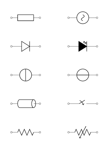
From the bottom left we have; a resistor, a variable resistor, a transmission line, a closing switch, a european current source, a european voltage source, an empty diode, a full led, a generic bipole and a sinusoidal voltage source.
Bipoles aren't the only type of component we can use.
We can also add in monopoles, tripoles, double bipoles, logic gates and amplifiers. However we can't use the to keyword to add these in as we've done before, because they don't naturally fit on a single line. Instead we use node notation. For example, this is how we would display an antenna:
(0,0) node[antenna] {}
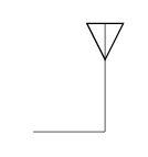
You can add text to the symbol using the curly brackets, but note that we still need to enter curly brackets even if we don't want to use them.
Here are some more examples:
(4,0) node[pmos] {}
(0,4) node[op amp] {}
(4,4) node[american or port] {}
(0,8) node[transformer] {}
(4,8) node[spdt] {}
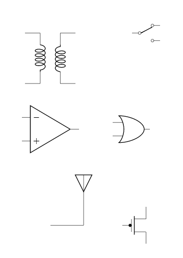
To link these with other components we would use the predefined node anchors. For more information about all the components available and how you link components using node anchors, take a look at the documentation.
This concludes our post on drawing electrical circuits. In the next post we'll look at drawing mind maps with TikZ.
If you want to play around with the flowchart we created in this post you can access it here.
All articles in this series
- Part 1: Basic Drawing;
- Part 2: Generating TikZ Code from GeoGebra;
- Part 3: Creating Flowcharts;
- Part 4: Circuit Diagrams Using Circuitikz;
- Part 5: Creating Mind Maps.
Please do keep in touch with us via Facebook, Twitter or via e-mail on our contact us page.