CircuiTikz package
Introduction
This article explains basic usage of the CircuiTikz package which provides a set of macros for typesetting electrical and electronic networks. To use this package it must be imported by writing
\usepackage{circuitikz}
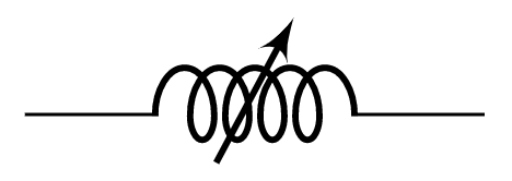
in your LaTeX document preamble. The environment circuitikz can then be used to typeset diagrams using TikZ syntax. CircuiTikz includes several nodes that can be used with standard TikZ syntax; the following example uses a node called variable cute inductor:
\documentclass{article}
\usepackage{circuitikz}
\begin{document}
\begin{center}
\begin{circuitikz}
\draw (0,0) to[ variable cute inductor ] (2,0);
\end{circuitikz}
\end{center}
\end{document}
This example produces the following output:
A working example
As noted, to draw electrical network diagrams you use standard TikZ syntax as demonstrated in the following, more complex, example:
\documentclass{article}
\usepackage{circuitikz}
\begin{document}
\begin{center}
\begin{circuitikz}[american voltages]
\draw
  (0,0) to [short, *-] (6,0)
  to [V, l_=$\mathrm{j}{\omega}_m \underline{\psi}^s_R$] (6,2)
  to [R, l_=$R_R$] (6,4)
  to [short, i_=$\underline{i}^s_R$] (5,4)
  (0,0) to [open, v^>=$\underline{u}^s_s$] (0,4)
  to [short, *- ,i=$\underline{i}^s_s$] (1,4)
  to [R, l=$R_s$] (3,4)
  to [L, l=$L_{\sigma}$] (5,4)
  to [short, i_=$\underline{i}^s_M$] (5,3)
  to [L, l_=$L_M$] (5,0);
\end{circuitikz}
\end{center}
\end{document}
This example produces the following output:
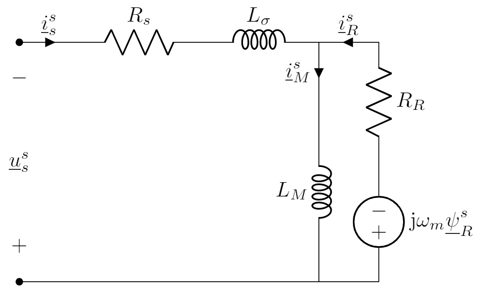
The nodes short, V, R and L are presented here, but there a lot more—some are listed in the next section.
List of some node types
Some of the elements provided by CircuiTikz are listed below, together with links that you can open directly in Overleaf to produce the tables. See the The circuitikz package documentation for additional node types.
Monopoles
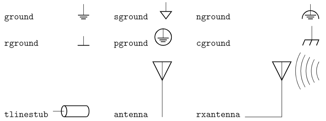
Open this table of circuitikz monopole nodes in Overleaf.
Bipoles
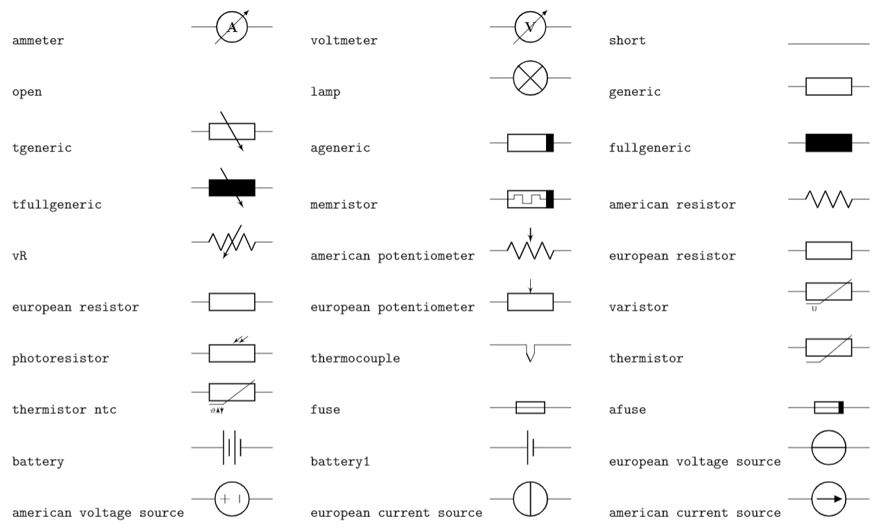
Open this table of circuitikz bipole nodes in Overleaf.
Diodes
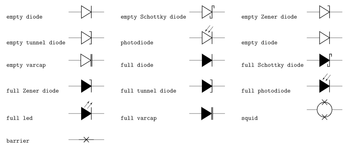
Open this table of circuitikz diode nodes in Overleaf.
Dynamical bipoles
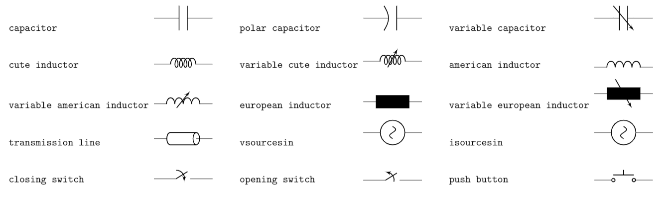
Open this table of circuitikz dynamical bipole nodes in Overleaf.
Further reading
For more information see: