Community articles — TikZ
Recent
Ce document regroupe les codes TIKZ des figures utilisées pour le cours "Champ magnétique créé par des courants électriques" situé à la page http://femto-physique.fr/electromagnetisme/biot_et_savart.php
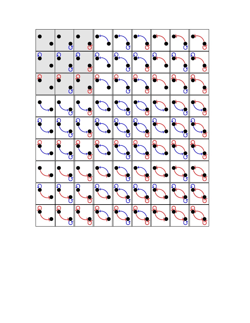
A diagram of 81 different ways (topologies) to connect two proteins. Every connection can be positive, negative or absent. Disconnected topologies are shaded gray. Author: Karthik Raman
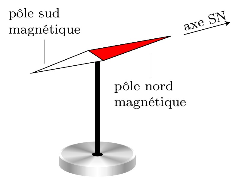
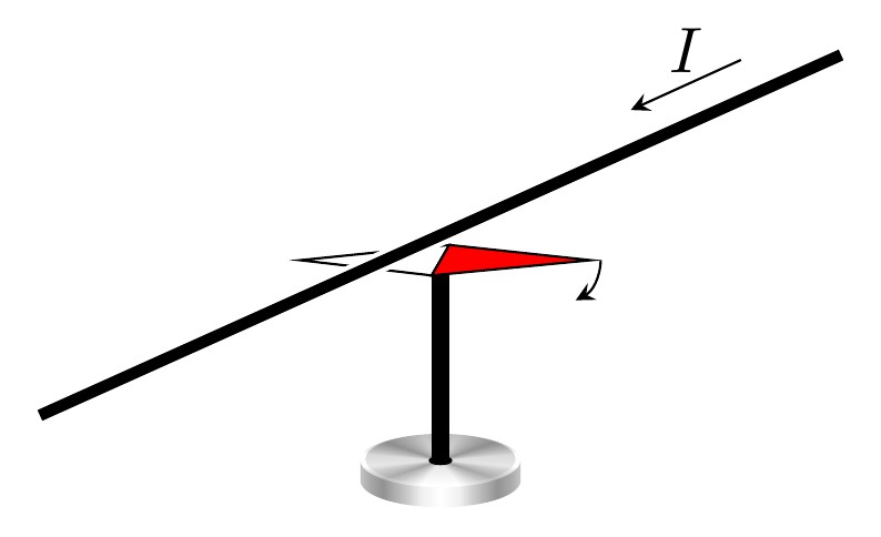
Ce document regroupe les codes TIKZ des figures utilisées pour le cours "Interactions magnétiques" situé à la page http://femto-physique.fr/electromagnetisme/Interaction magnétique.php
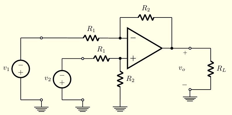
Este ejemplo representa el esquema de un amplificador diferencial construido con un amplificador operacional y cinco resistencias, el cual se usa para calcular la ganancia de la diferencia de dos señales independientes. Las notaciones son las siguientes: v1: tensión de entrada 1. v2: tensión de entrada 2. R1: resistencia. R2: resistencia. RL: resistencia de carga. vo: tensión de salida. Este esquema es una adaptación del que se encuentra en el la página 76, Capítulo 1 del texto "Electrónica, 2da Edición" de Allan R. Hambley, publicado en idioma español por la editorial Pearson Educación.
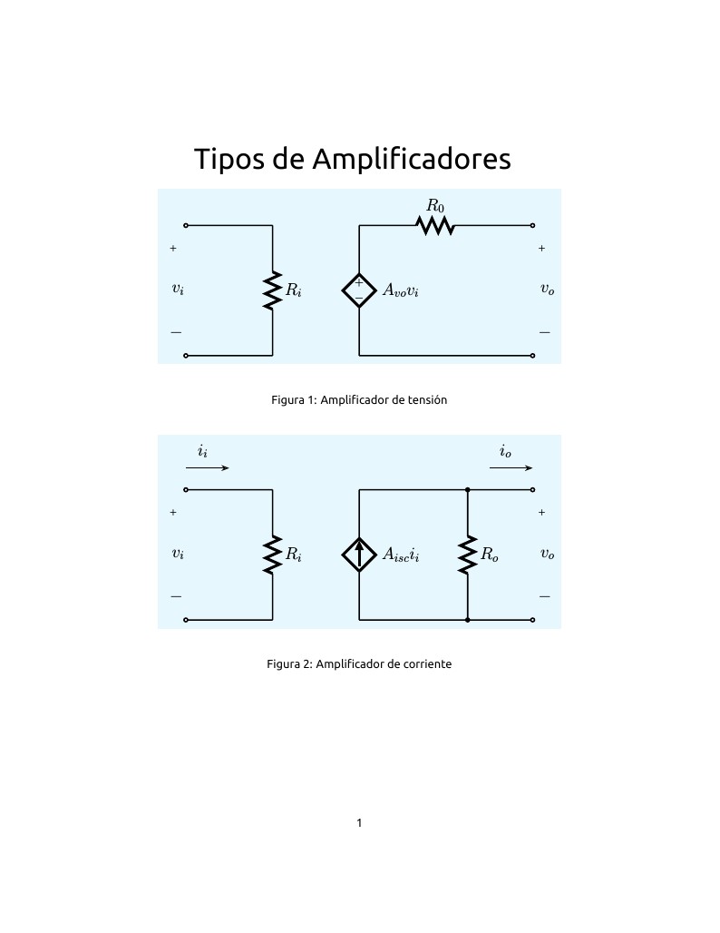
Este ejemplo representa los cuatro diferentes modelos de amplificadores existentes: amplificador de tensión, de corriente, de trasnconductancia y de transresistencia. Cualquier amplificador puede ser convertido en cualquier otro modelo. Las notaciones son las siguientes: vi: tensión de entrada. ii: corriente de entrada. Ri: resistencia de entrada. vo: tensión de salida. io: corriente de salida. Ro: resistencia de salida. Avo: Ganancia de tensión en vacío. Aisc: Ganancia de corriente en cortocircuito. Gmsc: Ganancia de transconductancia en cortocircuito, en Siemens. Rmoc: Ganancia de resistencia en circuito abierto, en Ohms. Las figuras con forma de diamante representan fuentes controladas por las tensiones o corrientes de entrada de cada una de los amplificadores. Los esquemas son una adaptación de los que se encuentran en el Capítulo 1 del texto "Electrónica, 2da Edición" de Allan R. Hambley, publicado en idioma español por la editorial Pearson Educación.
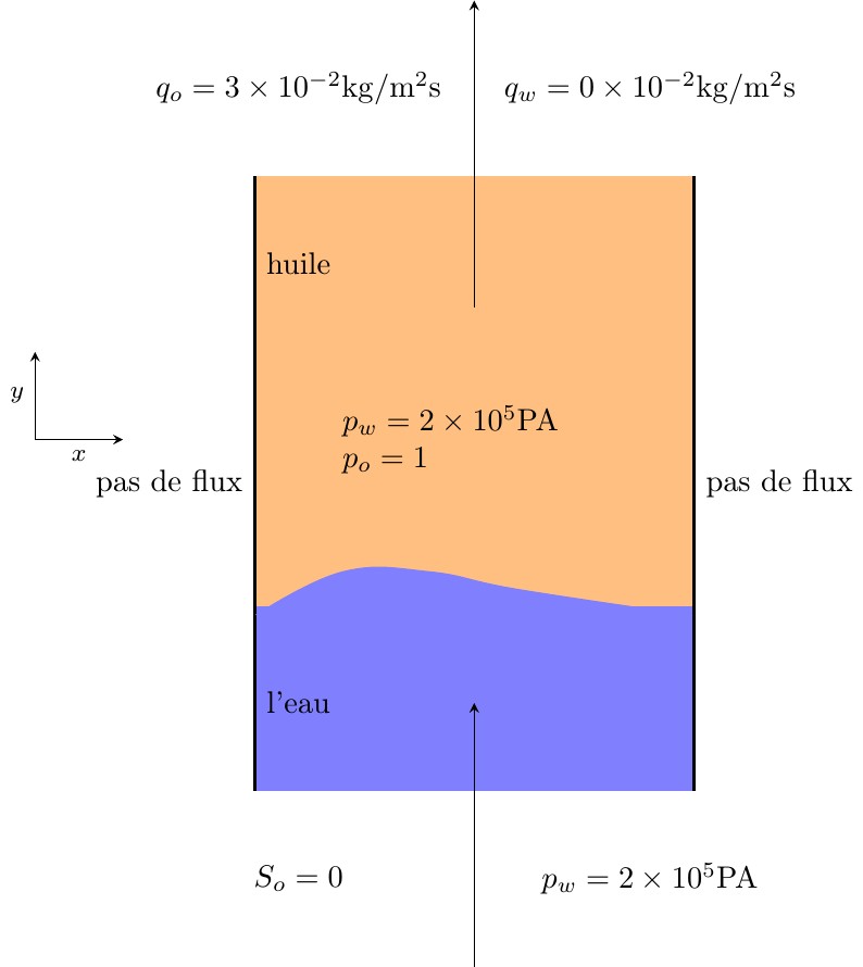
mechanics of fluid
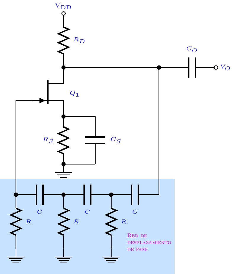
Este ejemplo representa un oscilador de desplazamiento de fase realizado con un transistor JFET Canal-N, dos resistencias y una red de re-alimentación constituida por tres resistencias y tres condensadores idénticos. El condensador CS se utiliza para una configuración de drenaje común y CO permite desacoplar la salida de la red de re-alimentación. Esta red es destacada en un recuadro coloreado de fondo, que se genera usando la biblioteca de TiKZ "backgrounds" Notaciones: Vo = tensión de salida. VDD= polarización positiva en el terminal de drenaje. Todos los componentes eléctricos y electrónicos carecen de valores o tipos. Este esquema es una adaptación de la figura que se encuentra en la página http://www.circuitstoday.com/fet-applications.
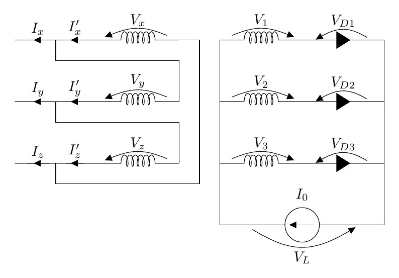
Transformador de potencia
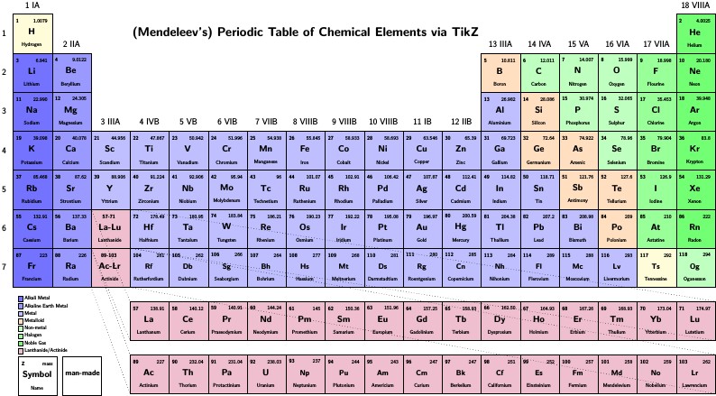
Copyright 2009 Ivan Griffin This work may be distributed and/or modified under the conditions of the LaTeX Project Public License, either version 1.3 of this license or (at your option) any later version. The latest version of this license is in http://www.latex-project.org/lppl.txt and version 1.3 or later is part of all distributions of LaTeX version 2005/12/01 or later. This work has the LPPL maintenance status `maintained'. The Current Maintainer of this work is Ivan Griffin This work consists of the files periodic_table.tex
\begin
Discover why over 25 million people worldwide trust Overleaf with their work.